Drag coefficient
From Wikipedia, the free encyclopedia
In fluid dynamics, the drag coefficient (commonly denoted as Cd, Cx or Cw) is a dimensionless quantity which is used to quantify the drag or resistance of an object in a fluid environment such as air or water. It is used in the drag equation, where a lower drag coefficient indicates the object will have less aerodynamic or hydrodynamic drag. The drag coefficient is always associated with a particular surface area.[1]
The drag coefficient of any object comprises the effects of the two basic contributors to fluid dynamic drag: skin friction and form drag. The drag coefficient of a lifting airfoil or hydrofoil also includes the effects of lift induced drag.[2][3] The drag coefficient of a complete structure such as an aircraft also includes the effects of interference drag.[4][5]
Contents |
[edit] Definition
The drag coefficient Cd is defined as:
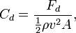
where
- Fd is the drag force, which is by definition the force component in the direction of the flow velocity,[6]
- ρ is the mass density of the fluid, [7]
- v is the speed of the object relative to the fluid, and
- A is the reference area.
The reference area depends on what type of drag coefficient is being measured. For automobiles and many other objects, the reference area is the frontal area of the vehicle (i.e., the cross-sectional area when viewed from ahead). For example, for a sphere A = πr2 (i.e., not the surface area).
For airfoils, the reference area is the chord of the airfoil multiplied with the length of span, which can be easily related to wing area. Since this tends to be a rather large area compared to the projected frontal area, the resulting drag coefficients tend to be low: much lower than for a car with the same drag, frontal area and at the same speed.
Airships and some bodies of revolution use the volumetric drag coefficient, in which the reference area is the square of the cube root of the airship volume. Submerged streamlined bodies use the wetted surface area.
Two objects having the same reference area moving at the same speed through a fluid will experience a drag force proportional to their respective drag coefficients. Coefficients for unstreamlined objects can be 1 or more, for streamlined objects much less.
[edit] Background

The drag equation
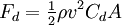
is essentially a statement that the drag force on any object is proportional to the density of the fluid, and proportional to the square of the relative speed between the object and the fluid.
Cd is not a constant but varies as a function of speed, flow direction, object shape, fluid density and fluid viscosity. Speed, kinematic viscosity and a characteristic length scale of the object are incorporated into a dimensionless quantity called the Reynolds number or Re. Cd is thus a function of Re. In compressible flow, the speed of sound is relevant and Cd is also a function of Mach number Ma.
For a certain body shape the drag coefficient Cd only depends on the Reynolds number Re, Mach number Ma and the direction of the flow. For low Mach number Ma, as usual for automobiles and sports planes, the drag coefficient is independent of Mach number. Also the variation with Reynolds number Re within a practical range of interest is usually small, while for cars at highway speed and aircraft at cruising speed the incoming flow direction is as well more-or-less the same. So the drag coefficient Cd can often be treated as a constant. [8]
For other objects, such as small particles, one can no longer consider that the drag coefficient is constant, but certainly is a function of Reynolds number. [9] [10] [11]
For a streamlined body to achieve a low drag coefficient the boundary layer around the body must remain attached to the surface of the body for as long as possible, causing the wake to be narrow. A broad wake results in high form drag. The boundary layer will remain attached longer if it is turbulent than if it is laminar. The boundary layer will transition from laminar to turbulent providing the Reynolds number of the flow around the body is high enough. Larger velocities, larger objects, and lower viscosities contribute to larger Reynolds numbers.[12]
At a low Reynolds number, the boundary layer around the object does not transition to turbulent but remains laminar, even up to the point at which it separates from the surface of the object. The drag coefficient Cd is no longer constant but varies with velocity, and the drag force Fd is proportional to v instead of v2. Reynolds number will be low for small objects, low velocities, and high viscosity fluids.[13]
A Cd equal to 1 would be obtained in a case where all of the fluid approaching the object is brought to rest, building up stagnation pressure over the whole front surface. The top figure shows a flat plate with the fluid coming from the right and stopping at the plate. The graph to the left of it shows equal pressure across the surface. In a real flat plate the fluid must turn around the sides, and full stagnation pressure is found only at the center, dropping off toward the edges as in the lower figure and graph. Only considering the front size, the Cd of a real flat plate would be less than 1; except that there will be suction on the back side: a negative pressure (relative to ambient). The overall Cd of a real square flat plate perpendicular to the flow is often given as 1.17. Flow patterns and therefore Cd for some shapes can change with the Reynolds number and the roughness of the surfaces.
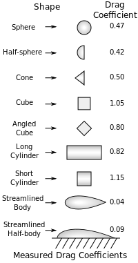
[edit] Drag coefficient Cd examples
As noted above, aircraft use wing area as the reference area when computing Cd, while automobiles (and many other objects) use frontal cross sectional area; thus, coefficients are not directly comparable between these classes of vehicles.
In general, Cd is not an absolute constant, for a given shape body. It varies with the speed of airflow (or more generally with Reynolds number). A smooth sphere, for example, has a Cd that varies from about 0.47 for laminar (slow) flow to 0.1 for separated (faster) flow.
|
|
[edit] Notes
- ^ McCormick, Barnes W. (1979), Aerodynamics, Aeronautics, and Flight Mechanics, p.24, John Wiley & Sons, Inc., New York ISBN 0-471-03032-5
- ^ Clancy, L.J., Aerodynamics, Section 5.18
- ^ Abbott, Ira H., and Von Doenhoff, Albert E., Theory of Wing Sections, Sections 1.2 and 1.3
- ^ NASA’s Modern Drag Equation
- ^ Clancy, L.J., Aerodynamics, Section 11.17
- ^ See lift force and vortex induced vibration for a possible force components transverse to the flow direction.
- ^ Note that for the Earth's atmosphere, the air density can be found using the barometric formula. Air is 1.293 kg/m3 at 0°C and 1 atmosphere
- ^ Clancy, L.J., Aerodynamics, Sections 4.15 and 5.4
- ^ Clift R., Grace J.R., Weber M.E., "Bubbles, drops, and particles", Academic Press NY (1978).
- ^ Briens C.L., Powder Technology, 67, 1991, 87-91.
- ^ Haider A., Levenspiel O., Powder Technology, 58, 1989, 63-70.
- ^ Clancy, L.J., Aerodynamics, Section 4.17
- ^ Clancy, L.J., Aerodynamics, Section 4.17
- ^ http://www.aerospaceweb.org/question/aerodynamics/q0184.shtml
- ^ http://www.lissys.demon.co.uk/samp1/index.html
[edit] References
- Clancy, L. J. (1975), Aerodynamics, Pitman Publishing Limited, London ISBN 0 273 01120 0
- Abbott, Ira H., and Von Doenhoff, Albert E. (1959), Theory of Wing Sections, Dover Publications Inc., New York, Standard Book Number 486-60586-8
- Hoerner, S. F. (1965), Fluid-Dynamic Drag, Hoerner Fluid Dynamics, Brick Town, N. J. USA

