Ocean thermal energy conversion
From Wikipedia, the free encyclopedia
Ocean thermal energy conversion (OTEC or OTE[1]) is a method for generating electricity which uses the temperature difference that exists between deep and shallow waters to run a heat engine. As with any heat engine, the greatest efficiency and power is produced with the largest temperature difference. This temperature difference generally increases with decreasing latitude, i.e. near the equator, in the tropics. Historically, the main technical challenge of OTEC was to generate significant amounts of power, efficiently, from this very small temperature ratio. Changes in efficiency of heat exchange in modern designs allow performance approaching the theoretical maximum efficiency.
The Earth's oceans are continually heated by the sun and cover nearly 70% of the Earth's surface; this temperature difference contains a vast amount of solar energy which can potentially be harnessed for human use. If this extraction could be made cost effective on a large scale, it could provide a source of renewable energy needed to deal with energy shortages, and other energy problems. The total energy available is one or two orders of magnitude higher than other ocean energy options such as wave power, but the small magnitude of the temperature difference makes energy extraction comparatively difficult and expensive, due to low thermal efficiency. Earlier OTEC systems had an overall efficiency of only 1 to 3% (the theoretical maximum efficiency lies between 6 and 7%[2]). Current designs under review will operate closer to the theoretical maximum efficiency. The energy carrier, seawater, is free, although it has an access cost associated with the pumping materials and pump energy costs. Although an OTEC plant operates at a low overall efficiency, it can be configured to operate continuously as a Base load power generation system. Any thorough Cost-benefit analysis should include these factors to provide an accurate assessment of performance, efficiency, operational and construction costs and returns on investment.

The concept of a heat engine is very common in thermodynamics engineering, and much of the energy used by humans passes through a heat engine. A heat engine is a thermodynamic device placed between a high temperature reservoir and a low temperature reservoir. As heat flows from one to the other, the engine converts some of the heat energy to work energy. This principle is used in steam turbines and internal combustion engines, while refrigerators reverse the direction of flow of both the heat and work energy. Rather than using heat energy from the burning of fuel, OTEC power draws on temperature differences caused by the sun's warming of the ocean surface.
The only heat cycle suitable for OTEC, is the Rankine cycle, using a low-pressure turbine. Systems may be either closed-cycle or open-cycle. Closed-cycle engines use working fluids that are typically thought of as refrigerants such as ammonia or R-134a. Open-cycle engines use the water heat source as the working fluid.
[edit] History
Even though an OTEC system is technologically advanced, the concept has a long history of development. There have been many periodic attempts to develop and refine the technology starting in the 1800s. In 1881, Jacques Arsene d'Arsonval, a French physicist, proposed tapping the thermal energy of the ocean. It was d'Arsonval's student, Georges Claude who actually built the first OTEC plant, in Cuba in 1930.[3] The system generated 22 kW of electricity with a low-pressure turbine.[4]
In 1931, Nikola Tesla released "On Future Motive Power" which covered an ocean thermal energy conversion system.[5] Although initially excited about the idea, Tesla ultimately came to the conclusion that the scale of engineering required for the project made it impractical for large scale development.
In 1935, Claude constructed another plant, this time aboard a 10,000-ton cargo vessel moored off the coast of Brazil. Weather and waves destroyed both plants before they could become net power generators.[4] (Net power is the amount of power generated after subtracting power needed to run the system.)
In 1956, French scientists designed a 3MW plant for Abidjan, Côte d'Ivoire. The plant was never completed, however, because large amounts of cheap oil became available in the 1950s making oil fired power plants more economical.[4]
In 1962, J. Hilbert Anderson and James H. Anderson, Jr. started designing a cycle to accomplish what Claude had not; they focused on developing new, more efficient component designs. After working through some of the problems in Claude's design they patented their new "closed cycle" design in 1967.[6]
The United States became involved in OTEC research in 1974, when the Natural Energy Laboratory of Hawaii Authority was established at Keahole Point on the Kona coast of Hawaii. The laboratory has become one of the world's leading test facilities for OTEC technology. Hawaii is often said to be the best location in the US for OTEC, due to the warm surface water, excellent access to very deep, very cold water, and because Hawaii has the highest electricity costs in the US.[7]
Although Japan has no potential OTEC sites it has been a major contributor to the development of the technology, primarily for export to other countries.[8] Beginning in 1970 the Tokyo Electric Power Company successfully built and deployed a 100 kW closed-cycle OTEC plant on the island of Nauru.[8] The plant, which became operational 1981-10-14, produced about 120 kW of electricity; 90 kW was used to power the plant itself and the remaining electricity was used to power a school and several other places in Nauru.[4] This set a world record for power output from an OTEC system where the power was sent to a real power grid.[9]
India piloted a 1 MW floating OTEC plant near Tamil Nadu. Its government continues to sponsor various research in developing floating OTEC facilities.[10]
[edit] Work principles
Some energy experts believe that if it could become cost-competitive with conventional power technologies, OTEC could produce gigawatts of electrical power, and in conjunction with electrolysis, could produce enough hydrogen to completely replace all projected global fossil fuel consumption.[citation needed] Managing costs is still a huge challenge, however. All OTEC plants require an expensive, large diameter intake pipe, which is submerged a kilometre or more into the ocean's depths, to bring very cold water to the surface.

[edit] Depending on the location
- Land based plant
- Shelf based plant
- Floating plant
[edit] Depending on the cycle used
- Open cycle
- Closed cycle
- Hybrid cycle
This cold seawater is an integral part of each of the three types of OTEC systems: closed-cycle, open-cycle, and hybrid. To operate, the cold seawater must be brought to the surface. This can be accomplished through direct pumping. A second method is to desalinate the seawater near the sea floor; this lowers its density, which will cause it to "float" up through a pipe to the surface.[11]
[edit] Closed-cycle

Closed-cycle systems use fluid with a low boiling point, such as ammonia, to rotate a turbine to generate electricity. Warm surface seawater is pumped through a heat exchanger where the low-boiling-point fluid is vaporized. The expanding vapor turns the turbo-generator. Then, cold, deep seawater—pumped through a second heat exchanger—condenses the vapor back into a liquid, which is then recycled through the system.
In 1979, the Natural Energy Laboratory and several private-sector partners developed the mini OTEC experiment, which achieved the first successful at-sea production of net electrical power from closed-cycle OTEC.[12] The mini OTEC vessel was moored 1.5 miles (2.4 km) off the Hawaiian coast and produced enough net electricity to illuminate the ship's light bulbs, and run its computers and televisions.
Then, the Natural Energy Laboratory in 1999 tested a 250 kW pilot closed-cycle plant, the largest of its kind ever put into operation. Since then, there have been no tests of OTEC technology in the United States, largely because the economics of energy production today have delayed the financing of a permanent, continuously operating plant.[citation needed]
Outside the United States, the government of India has taken an active interest in OTEC technology. India has built and plans to test a 1 MW, closed-cycle, floating OTEC plant.
[edit] Open-cycle
Open-cycle OTEC uses the tropical oceans' warm surface water to make electricity. When warm seawater is placed in a low-pressure container, it boils. The expanding steam drives a low-pressure turbine attached to an electrical generator. The steam, which has left its salt and contaminants behind in the low-pressure container, is pure fresh water. It is condensed back into a liquid by exposure to cold temperatures from deep-ocean water. This method has the advantage of producing desalinized fresh water, suitable for drinking water or irrigation.
In 1984, the Solar Energy Research Institute (now the National Renewable Energy Laboratory) developed a vertical-spout evaporator to convert warm seawater into low-pressure steam for open-cycle plants. Energy conversion efficiencies as high as 97% were achieved for the seawater to steam conversion process (overall efficiency of an OTEC system using a vertical-spout evaporator would still only be a few per cent). In May 1993, an open-cycle OTEC plant at Keahole Point, Hawaii, produced 50,000 watts of electricity during a net power-producing experiment.[13] This broke the record of 40,000 watts set by a Japanese system in 1982.[13]
[edit] Hybrid
A hybrid cycle combines the features of both the closed-cycle and open-cycle systems. In a hybrid OTEC system, warm seawater enters a vacuum chamber where it is flash-evaporated into steam, similar to the open-cycle evaporation process. The steam vaporizes the ammonia working fluid of a closed-cycle loop on the other side of an ammonia vaporizer. The vaporized fluid then drives a turbine to produce electricity. The steam condenses within the heat exchanger and provides desalinated water. (see heat pipe)
The electricity produced by the system can be delivered to a utility grid or used to manufacture methanol, hydrogen, refined metals, ammonia, and similar products.
[edit] Some proposed projects
OTEC projects on the drawing board include a small plant for the U.S. Navy base on the British-occupied island of Diego Garcia in the Indian Ocean. OCEES International, Inc. is working with the U.S. Navy on a design for a proposed 13 MW OTEC plant, which would replace the current power plant running diesel generators. The OTEC plant would also provide 1.25 MGD of potable water to the base. A private U.S. company also has proposed building at 10 MW OTEC plant on Guam.
[edit] Other related technologies
OTEC has important benefits other than power production.
[edit] Air conditioning
The cold (5°C, 41°F) seawater made available by an OTEC system creates an opportunity to provide large amounts of cooling to operations that are related to or close to the plant. The cold seawater delivered to an OTEC plant can be used in chilled-water coils to provide air-conditioning for buildings. It is estimated that a pipe 0.3-meters in diameter can deliver 0.08 cubic meters of water per second. (0.296 cubic meters of water per second or 4700 gallons per minute, is the maximum for a 0.3 meter diameter steel pipe) If 6°C water is received through such a pipe, it could provide more than enough air-conditioning for a large building. If this system operates 8000 hours per year and local electricity sells for 5¢-10¢ per kilowatt-hour, it would save $200,000-$400,000 in energy bills annually (U.S. Department of Energy, 1989).
The InterContinental Resort and Thalasso-Spa on the island of Bora Bora uses an OTEC system to air-condition its buildings.[14] The system accomplishes this by passing cold seawater through a heat exchanger where it cools freshwater in a closed loop system. This cool freshwater is then pumped to buildings and is used for cooling directly (no conversion to electricity takes place).
[edit] Chilled-soil agriculture
OTEC technology also supports chilled-soil agriculture. When cold seawater flows through underground pipes, it chills the surrounding soil. The temperature difference between plant roots in the cool soil and plant leaves in the warm air allows many plants that evolved in temperate climates to be grown in the subtropics. The Common Heritage Corporation, a former tenant at the Natural Energy Laboratory, and the holder of the patent on this process, maintained a demonstration garden with more than 100 different fruits and vegetables, many of which would not normally survive in Hawaii. No chilled soil agriculture is presently being undertaken at the Natural Energy Laboratory.
[edit] Aquaculture
Aquaculture is the most well-known byproduct of OTEC. It is widely considered to be one of the most important ways to reduce the financial and energy costs of pumping large volumes of water from the deep ocean. Deep ocean water contains high concentrations of essential nutrients that are depleted in surface waters due to biological consumption. This "artificial upwelling" mimics the natural upwellings that are responsible for fertilizing and supporting the world's largest marine ecosystems, and the largest densities of life on the planet.
Cold-water delicacies, such as salmon and lobster, thrive in the nutrient-rich, deep, seawater from the OTEC process. Microalgae such as Spirulina, a health food supplement, also can be cultivated in the nutrient rich water. Because the OTEC process uses cold, deep-ocean water and warm ocean water from the surface, it can be combined in various ratios to deliver sea water of a specific temperature conducive to maintaining an optimal environment for aquaculture. For example, Maine lobster could be grown in a tropical island environment in a temperature controlled mixture of cold and warm sea water.
Seafood not indigenous to tropical waters, can also be raised in pools created by OTEC-pumped water, such as Salmon, lobster, abalone, trout, oysters, and clams. This extends the variety of fresh seafood products available for nearby markets. Likewise, the low-cost refrigeration provided by the cold seawater can be used to upgrade or maintain the quality of indigenous fish, which tend to deteriorate quickly in warm tropical regions.
[edit] Desalination
Desalinated water can be produced in open- or hybrid-cycle plants using surface condensers. In a surface condenser, the spent steam is condensed by indirect contact with the cold seawater. This condensate is relatively free of impurities and can be collected and dispensed to local communities where supplies of natural freshwater for agriculture or drinking are limited. System analysis indicates that a 2-megawatt (electric) (net) plant could produce about 4300 cubic meters of desalinated water each day (Block and Lalenzuela 1985).
[edit] Hydrogen production
Hydrogen can be produced via electrolysis using electricity generated by the OTEC process. The steam generated can be used as a relatively pure medium for electrolysis with electrolyte compounds added to improve the overall efficiency. OTEC technology can be scaled to generate large quantities of hydrogen which can supply the burgeoning global marketplace. OTEC installations on islands, platforms, barges and ships have the potential for large scale, global hydrogen generation with supply to major ports via hydrogen tanker ships. For example, this is the method of delivery currently used to transport hydrogen to the Kennedy Space Center for use by NASA[citation needed]. The main challenges include the cost of production, transportation, and distribution, relative to other energy sources and fuels. Considering the increasing price of petroleum products on world markets, costs for large scale hydrogen production and distribution could be subject to change in a relatively small amount of time.
[edit] Mineral extraction
Another undeveloped opportunity, is the potential to mine ocean water for its 57 elements contained in salts and other forms and dissolved in solution. In the past, most economic analyses concluded that mining the ocean for trace elements dissolved in solution would be unprofitable, in part because much energy is required to pump the large volume of water needed. More significantly, it is often very expensive to separate the minerals from seawater. Generally this method is limited to minerals that occur in high concentrations, and can be extracted easily, such as magnesium.
However, with OTEC plants supplying the pumped water, the remaining problem is the cost of the extraction process. The Japanese recently began investigating the concept of combining the extraction of uranium dissolved in seawater with wave-energy technology. They found developments in other technologies (especially materials sciences) were improving the viability of mineral extraction processes that employ ocean energy.
[edit] Political concerns
Because OTEC facilities are more-or-less stationary surface platforms, their exact location and legal status may be affected by the United Nations Convention on the Law of the Sea treaty (UNCLOS). This treaty grants coastal nations 3-, 12-, and 200-mile zones of varying legal authority from land, creating potential conflicts and regulatory barriers to OTEC plant construction and ownership. OTEC plants and similar structures would be considered artificial islands under the treaty, giving them no legal authority of their own. OTEC plants could be perceived as either a threat or potential partner to fisheries management or to future seabed mining operations controlled by the International Seabed Authority.
[edit] Cost and economics
For OTEC to be viable as a power source in terms of global utilization, the technology must have equal tax and subsidy treatment as competing energy sources. Because OTEC systems have not yet been widely deployed, estimates of their costs are uncertain. One study [1] estimates power generation costs as low as US $0.07 per kilowatt-hour, compared with $0.07 for subsidized wind systems.[2]. [3].
Beneficial factors that should be taken into account include OTEC's status as a renewable resource (with no combustion or waste products or limited fuel supply), the amount of area in which it is available,[citation needed] (often within 20° of the equator) [4] the geopolitical effects of dependence and reliance on petroleum, the development of alternate forms of ocean power such as wave energy, tidal energy and methane hydrates, and the possibility of combining it with solar energy, aquaculture, refrigeration and air conditioning, hydrogen production or filtration for trace minerals to obtain multiple uses from a single pump system. See also [5].
[edit] Classification
OTEC systems can be classified as two types based on the thermodynamic cycle (1) Closed cycle and (2) Open cycle.
[edit] Variation of ocean temperature with depth
The total insolation received by the oceans = (5.457 × 10¹⁸ MJ/yr) × 0.7 = 1.9 × 10¹⁸ MJ/yr. (taking an average clearness index of 0.5)
Only 15% of this energy is retained as thermal energy.
We can use Lambert's law to quantify the solar energy absorption by water,
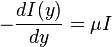
where, y is the depth of water, I is intensity and μ is the absorption coefficient. Solving the above differential equation,

The absorption coefficient μ may range from 0.05 m−1 for very clear fresh water to 0.5 m-1 for very salty water.
Since the intensity falls exponentially with depth y, the absorption is concentrated at the top layers. Typically in the tropics, surface temperature values are in excess of 25 °C, while 1 km below, the temperature is about 5 - 10 °C. Contrary to the usual cooking pot situation of heat supplied from the bottom surface, the warmer (and hence lighter) waters at the top means there are no thermal convection currents. Due to the very low temperature gradients, heat transfer by conduction is too low to cause any significant change, either. So with neither of the major mechanisms of heat transfer operating, the top layers remain hot and the lower layers remain cold. Thus it is like a practically infinite heat source and a practically infinite heat sink between a separation of about 1000 m that occurs naturally and allows the use of heat engines. This temperature difference varies with latitude and season, with the maximum at the tropical, subtropical and equatorial waters. Hence in general, the tropics are the best locations for OTEC systems.
[edit] Open/Claude cycle
In this scheme, warm surface water at around 27 °C is admitted into an evaporator in which the pressure is maintained at a value slightly below the saturation pressure.
Water entering the evaporator is therefore vaporized.

Where Hf is enthalpy of liquid water at the inlet temperature, T1.

This temporarily superheated water undergoes volume boiling as opposed to pool boiling in conventional boilers where the heating surface is in contact. Thus the water partially flashes to steam with a two-phase equilibrium prevailing. Suppose that the pressure inside the evaporator is maintained at the saturation pressure of water at T2. This process being iso-enthalpic,

Here, x2 is the fraction of water by mass that has vaporized. The warm water mass flow rate per unit turbine mass flow rate is 1/x2.
The low pressure in the evaporator is maintained by a vacuum pump that also removes the dissolved non-condensable gases from the evaporator. The evaporator now contains a mixture of water and steam of very low "quality" (steam content). The steam is separated from the water as saturated vapor. The remaining water is saturated and is discharged back to the ocean in the open cycle. The steam we have extracted in the process is a very low pressure, and very high specific volume working fluid. It expands in a special low pressure turbine.

Here, Hg corresponds to T2. For an ideal isentropic (reversible adiabatic) turbine,

The above equation corresponds to the temperature at the exhaust of the turbine, T5. x5,s is the mass fraction of vapor at state 5.
The enthalpy at T5 is,
This enthalpy is lower. The adiabatic reversible turbine work = H3-H5,s .
Actual turbine work WT = (H3-H5,s) × polytropic efficiency

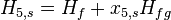
The condenser temperature and pressure are lower. Since the turbine exhaust will be discharged back into the ocean anyway, a direct contact condenser is used. Thus the exhaust is mixed with cold water from the deep cold water pipe which results in a near saturated water. That water is now discharged back to the ocean.
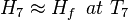
H6=Hf, at T5. T7 is the temperature of the exhaust mixed with cold sea water, as the vapour content now is negligible,
There are the temperature differences between stages: one between warm surface water and working steam, one between exhaust steam and cooling water, and one between cooling water reaching the condenser and deep water. These represent external irreversibilities that reduce the overall temperature difference.
The cold water flow rate per unit turbine mass flow rate,

Turbine mass flow rate, 
Warm water mass flow rate, 
Cold water mass flow rate 
[edit] Closed/Anderson cycle
Developed starting in the 1960s by J. Hilbert Anderson of Sea Solar Power, Inc. In this cycle, QH is the heat transferred in the evaporator from the warm sea water to the working fluid. The working fluid exits from the evaporator as a gas near its dew point.
The high-pressure, high-temperature gas then is expanded in the turbine to yield turbine work, WT. The working fluid is slightly superheated at the turbine exit and the turbine typically has an efficiency of 90% based on reversible, adiabatic expansion.
From the turbine exit, the working fluid enters the condenser where it rejects heat, -QC, to the cold sea water. The condensate is then compressed to the highest pressure in the cycle, requiring condensate pump work, WC. Thus, the Anderson closed cycle is a Rankine-type cycle similar to the conventional power plant steam cycle except that in the Anderson cycle the working fluid is never superheated more than a few degrees Fahrenheit. It is realized, owing to viscous effects, there must be working fluid pressure drops in both the evaporator and the condenser. These pressure drops, which are dependent on the types of heat exchangers used, must be considered in final design calculations but are ignored here to simplify the analysis. Thus, the parasitic condensate pump work, WC, computed here will be lower than if the heat exchanger pressure drops were included. The major additional parasitic energy requirements in the OTEC plant are the cold water pump work, WCT, and the warm water pump work, WHT. Denoting all other parasitic energy requirements by WA, the net work from the OTEC plant, WNP is

The thermodynamic cycle undergone by the working fluid can be analyzed without detailed consideration of the parasitic energy requirements. From the first law of thermodynamics, the energy balance for the working fluid as the system is

where WN = WT + WC is the net work for the thermodynamic cycle. For the special idealized case in which there is no working fluid pressure drop in the heat exchangers,

and

so that the net thermodynamic cycle work becomes

Subcooled liquid enters the evaporator. Due to the heat exchange with warm sea water, evaporation takes place and usually superheated vapor leaves the evaporator. This vapor drives the turbine and 2-phase mixture enters the condenser. Usually, the subcooled liquid leaves the condenser and finally, this liquid is pumped to the evaporator completing a cycle.
[edit] Working fluids
Various fluids have been proposed over the past decades to be used in closed OTEC cycle. A popular choice is ammonia, which has superior transport properties, easy availability, and low cost. Ammonia, however, is toxic and flammable. Fluorinated carbons such as CFCs and HCFCs would be a better choice, if they did not contribute to ozone layer depletion. Hydrocarbons too are good candidates, but they are highly flammable; in addition, this would put OTEC in competition with use of them directly as fuels. The power plant size is dependent upon the vapor pressure of the working fluid. For fluids with high vapor pressure, the size of the turbine and heat exchangers decreases while the wall thickness of the pipe and heat exchangers should increase to endure high pressure especially on the evaporator side.
[edit] Technical difficulties
[edit] Degradation of heat exchanger performance by dissolved gases
A very important technical issue pertaining to the Claude cycle is the performance of direct contact heat exchangers operating at typical OTEC boundary conditions. Many early Claude cycle designs used a surface condenser since their performance is well understood. However, direct contact condensers offer significant disadvantages. As the warm sea water rises in the intake pipes, the pressure decreases to the point where gas begins to evolve. If a significant amount of gas comes out of the solution, designing a gas trap before the direct contact heat exchangers may be justified. Experiments simulating conditions in the warm water intake pipe indicated about 30% of the dissolved gas evolve in the top 8.5 m of the tube. The tradeoff between pre-deaeration of the sea water and expulsion of all the non-condensable gases from the condenser is dependent on the gas evolution dynamics, deaerator efficiency, head loss, vent compressor efficiency and parasitic power. Experimental results have indicated vertical spout condensers perform some 30% better than falling jet types.
[edit] Degradation of heat exchanger performance by microbial fouling
Because raw seawater must be passed through the heat exchanger care must be taken to maintain good thermal conductivity. Biofouling layers as thin as 25 to 50 μm can degrade heat exchanger performance by as much as 40 to 50%.[2] A 1977 study in which mock heat exchangers were exposed to seawater for ten weeks concluded that although the level of microbial fouling was low, the thermal conductivity of the system was significantly impaired.[15] The apparent discrepancy between the level of fouling and the heat transfer impairment is the result of a thin layer of water trapped by the microbial growth on the surface of the heat exchanger.[15]
Another study, conducted in 1985 at Keahole Point, Hawaii, also concluded that microbial fouling degrades performance over time, as well as studying possible countermeasures to the degradation. The study determined that although regular brushing was able to remove most of the microbial layer, over longer periods of time a tough layer formed on the surface of the exchanger which could not be removed through simple brushing.[2] Additionally the study conducted trials of passing sponge rubber balls through the system. It concluded that although the ball treatment decreases the rate at which fouling occurs it was not enough to completely halt growth and brushing was occasionally necessary to restore full heat transfer capacity. Furthermore, the microbes began to regrow more quickly later in the experiment (i.e. brushing became necessary more often); this confirms the results of a previous study done under similar conditions.[16] The reason for the increased growth rate after subsequent cleanings appears to be the result of selection pressure acting on the microbial colony.[16]
In addition to physical cleaning methods the use of chlorination was examined. Both continuous use of 1 hour per day and intermittent periods of free fouling and then chlorination periods (again 1 hour per day) were studied. Like the foam rubber ball treatment chlorination did not completely stop microbial growth, it merely slowed it; however chlorination levels of .1 mg per liter treated for 1 hour per day slowed microbial growth appreciably and may prove effective in the long term operation of a plant.[2] Finally the study concluded that although microbial fouling was an issue for the warm surface water heat exchanger, the cold water heat exchanger suffered little or no biofouling and only minimal inorganic fouling.[2]
Besides water temperature, microbial fouling also shows a dependence on several other factors. The most obvious factor in microbial growth is nutrient levels, with growth occurring faster in more nutrient rich water.[17] The fouling rate also depends on the material used to construct the heat exchanger. Aluminum tubing slows the growth of microbial life, however the oxide layer which forms on the inside of the pipes makes cleaning more difficult leading to higher accumulated efficiency losses.[16] In contrast, titanium tubing allows biofouling to occur faster but cleaning is more effective than with aluminum.[16]
[edit] Improper sealing
The evaporator, turbine, and condenser operate in partial vacuum ranging from 3% to 1% atmospheric pressure. This poses a number of practical concerns. First, the system must be carefully sealed to prevent in-leakage of atmospheric air that can severely degrade or shut down operation. Second, the specific volume of low-pressure steam is very large compared to that of the pressurized working fluid used in the case of a closed cycle OTEC. This means components must have large flow areas to ensure steam velocities do not attain excessively high values.
[edit] Parasitic power consumption by exhaust compressor
An approach for reducing the exhaust compressor parasitic power loss is as follows. After most of the steam has been condensed by spout condensers, the non-condensible gas steam mixture is passed through a counter current region which increases the gas-steam reaction by a factor of five. The result is an 80% reduction in the exhaust pumping power requirements.
[edit] Energy from temperature difference between cold air and warm water
|
|
This section does not cite any references or sources. Please help improve this article by adding citations to reliable sources (ideally, using inline citations). Unsourced material may be challenged and removed. (March 2009) |
In winter in coastal Arctic locations, the seawater temperature can be 40 degrees Celsius (70 °F) warmer than the local air temperature. Technologies based on closed-cycle OTEC systems could exploit this temperature difference. The lack of the need for long pipes to extract deep seawater might make a system based on this concept less expensive than OTEC.
[edit] See also
[edit] References
- ^ Ocean Thermal Energy (OTE) at Sea Solar Power.com
- ^ a b c d e Berger LR, Berger JA (June 1986). "Countermeasures to Microbiofouling in Simulated Ocean Thermal Energy Conversion Heat Exchangers with Surface and Deep Ocean Waters in Hawaii". Appl. Environ. Microbiol. 51 (6): 1186–1198. PMID 16347076. PMC: 239043. http://aem.asm.org/cgi/pmidlookup?view=long&pmid=16347076.
- ^ Chiles, James (Winter 2009), "The Other Renewable Energy", Invention and Technology 23 (4): 24-35
- ^ a b c d Takahashi, Masayuki Mac; Translated by: Kitazawa, Kazuhiro and Snowden, Paul (2000). Deep Ocean Water as Our Next Natural Resource. Tokyo, Japan: Terra Scientific Publishing Company. ISBN 4-88704-125-x. http://www.terrapub.co.jp/e-library/dow/index.html.
- ^ Tesla, Nikola (December 1931). "On Future Motive Power". Everyday Science and Mechanics: 230–236. http://www.tesla.hu/tesla/articles/19311200/index.htm.
- ^ US patent 3312054, "Sea Water Power Plant", granted 1967-04-04
- ^ "Average Retail Price of Electricity to Ultimate Customers by End-Use Sector, by State". Energy Information Administration. September 2007. http://www.eia.doe.gov/cneaf/electricity/epm/table5_6_a.html.
- ^ a b Bruch, Vicki L. (April 1994) (PDF). An Assessment of Research and Development Leadership in Ocean Energy Technologies. SAND93-3946. Sandia National Laboratories: Energy Policy and Planning Department. http://www.osti.gov/bridge/servlets/purl/10154003-z9rVWD/native/10154003.PDF.
- ^ Mitsui, T.; Ito, F.; Seya, Y.; Nakamoto, Y. (September 1983). "Outline of the 100 kW OTEC Pilot Plant in the Republic of Nauru". IEEE Transactions on Power Apparatus and Systems PAS-102 (9): 3167–3171. doi:. http://library.greenocean.org/oteclibrary/otecdesigns/OTEC-nauru.pdf/view.
- ^ "Deep Pipelines for Ocean Thermal Energy Conversion". http://www.makai.com/p-otec.htm. Retrieved on 2009-02-16.
- ^ US patent 4311012, "Method and apparatus for transferring cold seawater upward from the lower depths of the ocean to improve the efficiency of ocean thermal energy conversion systems", granted 1982-01-19
- ^ Trimble, L.C.; Owens, W.L. (1980). "Review of mini-OTEC performance". Energy to the 21st century; Proceedings of the Fifteenth Intersociety Energy Conversion Engineering Conference 2: 1331–1338. http://adsabs.harvard.edu/abs/1980iece....2.1331T.
- ^ a b "Achievements in OTEC Technology". National Renewable Energy Laboratory. http://www.nrel.gov/otec/achievements.html.
- ^ "YouTube video on the OTEC air-conditioning system used at the InterContinental Resort and Thalasso-Spa on the island of Bora Bora". http://www.youtube.com/watch?v=zTGvPrrkVAA. Retrieved on 2007-05-28.
- ^ a b Aftring RP, Taylor BF (October 1979). "Assessment of Microbial Fouling in an Ocean Thermal Energy Conversion Experiment". Appl. Environ. Microbiol. 38 (4): 734–739. PMID 16345450. PMC: 243568. http://aem.asm.org/cgi/pmidlookup?view=long&pmid=16345450.
- ^ a b c d Nickels JS, Bobbie RJ, Lott DF, Martz RF, Benson PH, White DC (June 1981). "Effect of Manual Brush Cleaning on Biomass and Community Structure of Microfouling Film Formed on Aluminum and Titanium Surfaces Exposed to Rapidly Flowing Seawater". Appl. Environ. Microbiol. 41 (6): 1442–1453. PMID 16345798. PMC: 243937. http://aem.asm.org/cgi/pmidlookup?view=long&pmid=16345798.
- ^ Trulear, MG; Characklis, WG (September 1982). "Dynamics of Biofilm Processes". Journal of the Water Pollution Control Federation 54 (9): 1288–1301. http://md1.csa.com/partners/viewrecord.php?collection=ENV&recid=8301080&uid=792056511&q=&uid=792056511&q=&uid=792056511&setcookie=yes.
[edit] Sources
- Renewable Energy From The Ocean - A Guide To OTEC, William H. Avery, Chih Wu, Oxford University Press, 1994. Covers the OTEC work done at the Johns Hopkins Applied Physics Laboratory from 1970–1985 in conjunction with the Department of Energy and other firms.
[edit] External links
- - Ocean Energy Council: How does OTEC work?
- nrel.gov - what is OTEC?
- US Department of Energy, Information Resources
- Wired Magazine's interview with John Piña Craven on the future of OTEC
- OTEC News - a news site about OTEC
- 2007 edition of the Survey of Energy Resources produced by the World Energy Council
- The Green Ocean Project - OTEC Library
- The Green Ocean Project (CO2 release)
- Plumbing the oceans could bring limitless clean energy
- OTEC is an adult science fiction novel about people living on a Seacrete floating city powered by thermal energy conversion.
- [6] Maximum water flow capacity of steel pipes - dimensions ranging 2 - 24 inches
The Engineering Toolbox.
|
||||||||||||||||||||


