Halbach array
From Wikipedia, the free encyclopedia

A Halbach array is a special arrangement of permanent magnets that augments the magnetic field on one side of the array while cancelling the field to near zero on the other side. In the diagram, the magnetic field is enhanced on the bottom side and cancelled on the top side (a one-sided flux).
The rotating pattern of permanent magnets (on the front face; on the left, up, right, down) can be continued indefinitely and have the same effect. The effect of this arrangement is roughly similar to many horseshoe magnets placed adjacent to each other, with similar poles touching.
The effect was discovered by Mallinson in 1973, and these 'one-sided flux' structures were initially described by him as a 'curiosity', although he recognised at the time the potential for significant improvements in magnetic tape technology.[1]
"In the 1980s, the late Klaus Halbach, a physicist at Lawrence Livermore National Laboratory, invented the Halbach array to focus accelerator particle beams."[2]
Contents |
[edit] Flat Halbach arrays
[edit] Magnetization
Although this magnetic flux distribution seems somewhat counter-intuitive to those familiar with, for example, bar magnets or solenoids, the reason for this flux distribution can be intuitively visualised using Mallinson’s original diagram (note this uses the negative y-component, unlike the diagram in Mallinson’s paper). The diagram shows the field from a strip of ferromagnetic material with alternating magnetization in the y direction (top left) and in the x direction (top right). Note that the field above the plane is in the same direction for both structures, but the field below the plane is in opposite directions. The effect of superimposing both of these structures is shown in the figure at the bottom:


The crucial point is that the flux will cancel below the plane and reinforce itself above the plane. In fact, any magnetization pattern where the components of magnetization are π / 2 out of phase with each other will result in a one-sided flux. The mathematical transform which shifts the phase of all components of some function by π / 2 is called a Hilbert transform; the components of the magnetization vector can therefore be any Hilbert transform pair (the simplest of which is simply sin(x)cos(y), as shown in the diagram above).
The advantages of one sided flux distributions are twofold:
- The field is twice as large on the side on which the flux is confined (in the idealised case).
- No stray field is produced (in the ideal, infinite length case) on the opposite side. This helps with field confinement, usually a problem in the design of magnetic structures.
Halbach arrays can be rolled into a cylindrical shape, known as a Halbach cylinder.
The field on the non cancelling side of a continuously varying infinite array is of the form:[3]
- F(x,y) = F0eiλxe − λy
Where:
- F(x,y) is the field in the form Fx + Fyi
- F0 is the magnitude of the field at the surface of the array
- λ is the spatial frequency
[edit] Applications
Although one-sided flux distributions may seem somewhat abstract, they have a surprising number of applications ranging from the humble refrigerator magnet through industrial applications such as the brushless AC motor and magnetic coupling, to high-tech applications such as wiggler magnets used in particle accelerators and free electron lasers. This device is also a key component of the Inductrack maglev system. The Halbach arrays repel buried loops of wire after they have been accelerated to speed, lifting the train.
One-sided flux theory could also explain the lack of magnetic field on celestial bodies, such as the moon and Mars, due to the cooling process after the formation of such bodies ‘freezing in’ a spherical internal one-sided flux distribution, giving rise to zero field external to the planet.[4]
The simplest example of a one sided flux magnet is a refrigerator magnet. These are usually composed of powdered ferrite in a binder such as plastic or rubber. The extruded magnet is exposed to a rotating field giving the ferrite particles in the magnetic compound a magnetization resulting in a one-sided flux distribution. This distribution increases the holding force of the magnet when placed on a permeable surface, compared to the holding force from, say, a uniform magnetization of the magnetic compound.

Scaling up this design and adding a top sheet gives a wiggler magnet, used in synchrotrons and free electron lasers. Wiggler magnets ‘wiggle’ or oscillate an electron beam perpendicular to the magnetic field. As the electrons are undergoing acceleration they radiate electromagnetic energy and these photons can be trapped between two parallel mirrors that form a resonant cavity similar to that of a conventional laser.
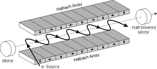
The design shown above is usually known as a Halbach wiggler. The magnetization vectors in the magnetized sheets rotate in the opposite senses to each other; above, the top sheet’s magnetization vector rotates clockwise and the bottom sheet’s magnetization vector rotates counter-clockwise. This design is chosen so that the x-components of the magnetic fields from the sheets cancel and the y-components reinforce so that the field is given by
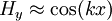
where k is the ‘wavenumber’ of the magnetic sheet given by the spacing between magnetic blocks with the same magnetization vector.
[edit] Halbach cylinder
A Halbach cylinder is a magnetized cylinder composed of ferromagnetic material producing (in the idealised case) an intense magnetic field confined entirely within the cylinder with zero field outside. The cylinders can also be magnetized such that the magnetic field is entirely outside the cylinder, with zero field inside. Several magnetization distributions are shown below:

The direction of magnetization within the ferromagnetic material is given by
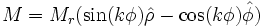

where Mr is the ferromagnetic remanence (T/m). A choice of +k gives an internal magnetic field and -k gives an external magnetic field.
Ideally, these structures would be created from an infinite length cylinder of magnetic material with the direction of magnetization continuously varying. The magnetic flux produced by this ideal design would be perfectly uniform and be entirely confined to the bore of the cylinder. Of course, the ideal case of infinite length is not realisable and in practice the finite length of the cylinders produces end effects which introduce non-uniformities in the field within the bore. The difficulty of manufacturing a cylinder with a continuously varying magnetization also usually leads to the design being broken into segments.
These cylindrical structures are used in devices such as brushless AC motors, magnetic couplings and high field cylinders. Both brushless motors and coupling devices use multipole field arrangements:
- Brushless motors typically use cylindrical designs in which all the flux is confined to the centre of the bore (such as k = 3 above, a six pole rotor) with the AC coils also contained within the bore. Such self-shielding motors designs are more efficient and produce higher torque than conventional motor designs.
- Magnetic coupling devices transmit torque through magnetically transparent barriers (that is the barrier is non-magnetic or is magnetic but is not affected by an applied magnetic field), for instance between sealed containers or pressurised vessels. The optimal torque couplings consists of a pair of coaxially nested cylinders with opposite +k and -k flux magnetization patterns, as -k magnetization patterns produce fields entirely external to the cylinder. In the lowest energy state, the outer flux of the inner cylinder exactly matches the internal flux of the outer cylinder. Rotating one cylinder relative to the other from this state results in a restoring torque.
[edit] Uniform Fields

For the special case of k = 2, the field inside the bore is uniform, and is given by:

where the inner and outer cylinder radii are Ro and Ri, respectively. H is in the y direction. This is the simplest form of the Halbach cylinder, and it can be seen that if the ratio of outer to inner radii is greater than e the flux inside the bore actually exceeds the remanence of the magnetic material used to create the cylinder.
This cylindrical design is only one class of design which produces a uniform field inside a cavity within an array of permanent magnets. Other classes of design include wedge designs, proposed by Abele and Jensen in which wedges of magnetized material are arranged to provide uniform field within cavities inside the design as shown below.

The direction of magnetization of the wedges in (A) can be calculated using a set of rules given by Abele, and allows for great freedom in the shape of the cavity. Another class of design is the magnetic mangle (B), proposed by Coey and Cugat, in which uniformly magnetized rods are arranged such that their magnetization matches that of a Halbach cylinder, as shown for a six rod design. This design greatly increases access to the region of uniform field, at the expense of the volume of uniform field being smaller than in the cylindrical designs (although this area can be made larger by increasing the number of component rods). Rotating the rods relative to each other results in many possibilities including a dynamically variable field and various dipolar configurations. It can be seen that these designs are closely related to the k = 1 Halbach cylinder. Other very simple designs for a uniform fields include separated magnets with soft iron return paths, as shown in figure (C).
If a k = 2 cylinder is cut and unrolled flat, the resulting structure is a Halbach array.
[edit] Varying the field
Halbach cylinders give a static field. However cylinders can be nested, and by rotating one cylinder relative to the other, cancellation of the field and adjustment of the direction can be achieved. [5]
[edit] Halbach spheres
If the two dimensional magnetic distribution patterns of the Halbach cylinder are extended to three dimensions, the result is the Halbach sphere. These designs have an extremely uniform field within the interior of the design, as they are not affected by the 'end effects' prevalent in the finite length cylinder design. The magnitude of the uniform field for a sphere also increases to 4/3 the amount for the ideal cylindrical design with the same inner and outer radii. However, being spherical, access to the region of uniform field is usually restricted to a narrow hole at the top and bottom of the design.
Higher fields are possible by optimising the spherical design to take account of the fact that it is composed of point dipoles (and not line dipoles). This results in the stretching of the sphere to an elliptical shape and having a non-uniform distribution of magnetization over the component parts of the sphere. Using this method, as well as soft pole pieces within the design, 4.5 T in a working volume of 20 mm3 was achieved by Bloch et al. in 1998 and this was increased further to 5 T in 2000, although over a smaller working area of 0.05 mm . As hard materials are temperature dependent, refrigeration of the entire magnet array can increase the field within the working area further as shown by Kumada et al. This group also reported development of a 5.16 T Halbach dipole cylinder in 2003.
[edit] See also
- Supermagnet
- Permanent magnet
- Strong focusing
- Inductrack uses Halbach arrays to generate strong fields for maglev
[edit] References
- ^ J.C. Mallinson, "One-Sided Fluxes — A Magnetic Curiosity?", IEEE Transactions on Magnetics, 9, 678-682, 1973
- ^ "Magnetically levitated train takes flight"
- ^ [1]
- ^ J.C.Mallinson, H.Shute and D. Wilton, "One-Sided Fluxes in Planar, Cylindrical and Spherical Magnetized Structures" IEEE Transactions on Magnetics,36, 2,Mar 2000
- ^ Tip Magazine: Magnets, Markets, and Magic Cylinders The Industrial Physicist by Michael Coey and Denis Weaire
- K. Halbach, Nuclear Instruments and Methods, 169, 1, (1980)
- J. M. D. Coey and T.R. Ní Mhíocháin, "Permanent Magnets", High Magnetic Fields: Science and Technology, Volume 1, ed. F. Herlach and N. Miura, World Scientific Publishing, p25 - 47 (2003)
- O. Cugat and F. Bloch, "4-Tesla Permanent Magnetic Flux Source", Proc. 15th International Workshop on Rare Earth Magnets and Their Applications, published by MAT INFO, Dresden 1998, p807 (1998)

