Parity bit
From Wikipedia, the free encyclopedia
| 7 bits of data (number of 1s) |
8 bits including parity | |
| even | odd | |
| 0000000 (0) | 00000000 | 10000000 |
| 1010001 (3) | 11010001 | 01010001 |
| 1101001 (4) | 01101001 | 11101001 |
| 1111111 (7) | 11111111 | 01111111 |
A parity bit is a bit that is added to ensure that the number of bits with value of one in a given set of bits is always even or odd. Parity bits are used as the simplest error detecting code.
As for binary digits, there are two variants of parity bits: even parity bit and odd parity bit. An even parity bit is set to 1 if the number of ones in a given set of bits is odd (making the total number of ones, including the parity bit, even). An odd parity bit is set to 1 if the number of ones in a given set of bits is even (making the total number of ones, including the parity bit, odd). Even parity is actually a special case of a cyclic redundancy check (CRC), where the 1-bit CRC is generated by the polynomial x+1.
If the parity bit is present but not used, it may be referred to as mark parity, where the parity bit is always 1, or as space parity, where the bit is always 0.
Contents |
[edit] Error detection
If an odd number of bits (including the parity bit) are changed in transmission of a set of bits then parity bit will be incorrect and will thus indicate that an error in transmission has occurred. Therefore, parity bit is an error detecting code, but is not an error correcting code as there is no way to determine which particular bit is corrupted. The data must be discarded entirely, and re-transmitted from scratch. On a noisy transmission medium a successful transmission could take a long time, or even never occur. Parity does have the advantage, however, that it is about the best possible code that uses only a single bit of space and it requires only a number of XOR gates to generate. See Hamming code for an example of an error-correcting code.
Parity bit checking is used often for transmission of ASCII characters, since they have 7 bits and the 8th bit can conveniently be used as a parity bit.
For example, our parity bit can be computed as follows assuming we are sending a simple 4-bit value 1001, with the parity bit following on the right, and ^ denoting XOR gate:
Transmission sent using even parity:
A wants to transmit:          1001
A computes parity bit value:  1^0^0^1 = 0
A adds parity bit and sends:  10010
B receives:                   10010
B computes parity:            1^0^0^1^0 = 0
B reports correct transmission after observing expected even result.
Transmission sent using odd parity:
A wants to transmit:          1001
A computes parity bit value:  ~(1^0^0^1) = 1
A adds parity bit and sends:  10011
B receives:                   10011
B computes overall parity:    1^0^0^1^1 = 1
B reports correct transmission after observing expected odd result.
This mechanism enables the detection of single bit errors, because if one bit gets flipped due to line noise, there will be an incorrect number of ones in the received data. In the two examples above, B's calculated parity value matches the parity bit in its received value, indicating there are no single bit errors. Consider the following example with a transmission error in the second bit:
Transmission sent using even parity:
A wants to transmit:          1001
A computes parity bit value:  1^0^0^1 = 0
A adds parity bit and sends:  10010
*** TRANSMISSION ERROR ***
B receives:                   11010
B computes overall parity:    1^1^0^1^0 = 1
B reports incorrect transmission after observing unexpected odd result.
B's calculated parity value (1) does not match the parity bit (0) in its received value, indicating the bit error. Here's the same example but now the parity bit itself gets corrupted:
A wants to transmit:          1001
A computes even parity value: 1^0^0^1 = 0
A sends:                      10010
*** TRANSMISSION ERROR ***
B receives:                   10011
B computes overall parity:    1^0^0^1^1 = 1
B reports incorrect transmission after observing unexpected odd result.
Once again, B's computes an odd overall parity, indicating the bit error.
There is a limitation to parity schemes. A parity bit is only guaranteed to detect an odd number of bit errors. If an even number of bits have errors, the parity bit records the correct number of ones, even though the data is corrupt. (See also error detection and correction.) Consider the same example as before with an even number of corrupted bits:
A wants to transmit:          1001
A computes even parity value: 1^0^0^1 = 0
A sends:                      10010
*** TRANSMISSION ERROR ***
B receives:                   11011
B computes overall parity:    1^1^0^1^1 = 0
B reports correct transmission though actually incorrect.
B observes even parity, as expected, thereby failing to catch the two bit errors.
[edit] Usage
Because of its simplicity, parity is used in many hardware applications where an operation can be repeated in case of difficulty, or where simply detecting the error is helpful. For example, the SCSI and PCI buses use parity to detect transmission errors, and many microprocessor instruction caches include parity protection. Because the I-cache data is just a copy of main memory, it can be thrown away and re-fetched if it is found to be corrupted.
In serial data transmission, a common format is 7 data bit, an even parity bit, and one or two stop bits. This format neatly accommodates all the 7-bit ASCII characters in a convenient 8-bit byte. Other formats are possible; 8 bits of data plus a parity bit can convey all 8-bit byte values.
In serial communication contexts, parity is usually generated and checked by interface hardware (e.g., a UART) and, on reception, the result made available to the CPU (and so to, for instance, the operating system) via a status bit in a hardware register in the interface hardware. Recovery from the error is usually done by retransmitting the data, the details of which are usually handled by software (e.g., the operating system I/O routines).
[edit] Parity block
A parity block is used by certain RAID levels. Redundancy is achieved by the use of parity blocks. If a single drive in the array fails, data blocks and a parity block from the working drives can be combined to reconstruct the missing data.
Given the diagram below, where each column is a disk, assume A1 = 00000111, A2 = 00000101, and A3 = 00000000. Ap, generated by XORing A1, A2, and A3, will then equal 00000010. If the second drive fails, A2 will no longer be accessible, but can be reconstructed by XORing A1, A3, and Ap:
A1 XOR A3 XOR Ap = 00000101
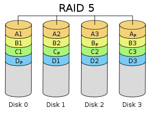
Note: Data blocks are in the format A#, parity blocks Ap.
[edit] History
A "parity track" was present on the first magnetic tape data storage in 1951. Parity in this form, applied across multiple parallel signals, is known as a transverse redundancy check. This can be combined with parity computed over multiple bits sent on a single signal, a longitudinal redundancy check. In a parallel bus, there is one longitudinal redundancy check bit per parallel signal.

